
DevLog #3 – Config your 3D world for pixel art rendering
Hello everyone!
Last week, we talked about why we switched to 3D for project “Stasis”. Let’s now show some tricks we use in Godot to still achieve a nice pixel graphics look!
Our game has a top-down view, but we still have some choices to make in terms of perspective. The world to explore will have many floors and cliffs of different heights. That’s why we should think about how we represent depth. We looked at some of our favorite games of the genre and finally decided to discard vertical distortion (for example like CrossCode does). This means that all edges of a cube have the same length on the screen, even the ones going from foreground to the background. This comes with a few drawbacks in terms of readability, but we really like the style and we will show further below how we mitigate this problem.
Here is an example we made with Aseprite when working on a spritesheet for the first zone of the game:
Camera setup
Since we are working with 3D nodes in the Godot engine, the first step is to properly configure our camera. We set the orthographic projection mode, and rotate of -45° around the x axis to simulate the top down view. Now, if we place a cube mesh in our scene, it looks good, but we have vertical distortion. To fix this, we adapt the size of our world. To account for the projection, the unit size of our tiles is not 1 x 1 x 1 but 1 x √(2) x √(2), as illustrated below:
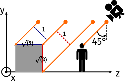
As a consequence, every node that displays a texture in our world is scaled by √(2) on both the y and z axis. The x scale stays at 1. For entities and objects, we use mostly Sprite3D nodes, either horizontally of vertically, and we animate them with a spritesheet like in 2D. We decided that 1 unit in 3D corresponds to 16 pixels and thus set the pixel_size parameter to 1/16 = 0.0625. For world terrain, we use cube, plane or quad meshes with spatial material and albedo textures.
Another challenge is to configure the camera size so that the world view has the wanted dimensions. Our game has a resolution of 848x477. Thus, we set the camera to keep the width, and the size to 848/16 = 53.
Now, when we run the scene, everything looks as expected and we already have a nice 2D pixel art look!
Snapping to the grid
To obtain a pixel perfect rendering, we also need to snap all node positions to the pixel grid, otherwise we would see some visual glitches. This is similar to what we usually do when working in 2D, except we here don’t snap values to Vector2(1, 1), but to Vector3(0.0625, 0.0625 * sqrt(2), 0.0625 * sqrt(2)). This is somewhat more tedious since there is no editor feature to automatically ensure this as far as we know. Fortunately, we rarely instantiate nodes manually in the 3D workspace, we mainly work with the 2D workspace and our custom tools automatically create 3D nodes at the right positions—we will talk more about our map editor in a future devlog. Snapping the position to the pixel grid should also be done at all time when entities (or the camera) move into the scene, we do this for each frame in the _physics_process method after movement computations:
# In physics_utils.gd
const PIXEL_SIZE = 1.0 / 16.0
const PIXEL_VECTOR = Vector3(PIXEL_SIZE, PIXEL_SIZE * sqrt(2), PIXEL_SIZE * sqrt(2))

# In player.gd
global_transform.origin = global_transform.origin.snapped(PhysicsUtils.PIXEL_VECTOR)
Transparent pipeline
We experienced some issues when working with transparent objects. Godot uses a different pipeline for them—you can learn more about this here—and thus draws nodes sometimes in the wrong order. A good advice is to work as much as possible with opaque objects and to activate the transparent flag only when absolutely needed. Because we use a lot of Sprite3D nodes with animation spritesheets, we require this flag quite often. After some testing, we found out that disabling shadows instead of using opaque pre-pass in the Sprite3D node was enough to make it work. To still obtain shadows, we add a mesh set to shadows only. It will not reflect perfectly the sprite shape, but basic sphere and capsules shapes are good enough for our needs.
Improve world readability
Since we have no perspective and no vertical distortion, we may sometimes struggle to perceive depth and altitude. To make level more readable, we adopted a few tricks.
- Adding borders. This means we don’t even need to use different textures for floors of different heights. Borders tell the player where edges are and where they can jump off.
- Level of details. For interior rooms, we use a less-detailed texture for background walls. It helps your eyes focus on other walls where platforming may happen. Detail contrast is actually a very powerful way to control where the player should look at first.
- Darker diagonal walls. When building our mesh library, we darken a bit meshes that correspond to diagonal walls. At the intersection with a right wall, the contrast indicates a sharp edge. We feel it helps to understand the depth.
- Shadows. This one is the most important. Shadows help a lot to grasp the depth. Compared to our previous 2D approach, we don’t need to fake shadows anymore: we add a DirectionalLight node and the 3D engine takes care of all computations. This comes at the cost of performance but the readability improvements are worth it. They are pretty nice too.
That’s all for this week! Tell us in the comments what you think of the last screenshot! We will also try to answer some technical questions if you want to ask some.
Until next time!